The tensioned wire wheel is one of the most elegant, successful, and enduring technologies of the 19th century. Although materials and manufacturing methods have continually improved, the basic design of the bicycle wheel has not changed fundamentally in the last century: a central hub is connected to a hoop-shaped outer rim by a set of tensioned spokes, which are threaded into adjustable spoke nipples set into the inside of the rim. The bicycle wheel is a type of tensegrity structure: it combines elements which only carry tension (spokes) with elements which predominately carry compression (rim). When the weight of the rider is applied to the hub (through the ball bearings) the load is transmitted to the rim (and ultimately the road) primarily due to the shortening of the spokes directly underneath the hub.
When a wheelbuilder builds a wheel, they must make many decisions, including the components, geometry, materials, and spoke pattern. Some of these decisions are made for aesthetic reasons, but many of these choices can have a profound impact on the performance and durability of the wheel. I created the Bicycle Wheel Simulator to simulate the mechanical response of a bicycle wheel to different loads. This program can be used to calculate the stiffness (along different directions), spoke tensions, and deformation of a custom wheel. I hope it can be useful to wheelbuilders, mechanics, and the merely curious.
Examples
Many wheel enthusiasts are familiar with Jobst Brandt's calculations of wheel deformation under weight, braking and pedaling forces. His simulation neglected lateral deformation (his model is 2-dimensional), but nevertheless demonstrated some important points about how wheels work. Below are some examples of calculations using the Bicycle Wheel Simulator.
Weight of the bike and rider
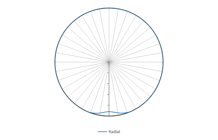
When the wheel supports weight, the bottom of the rim flattens out very slightly. The reduction in spoke tensions below the hub balance the downward force applied by the dropouts.
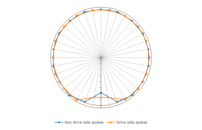
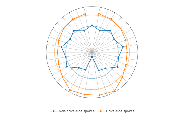
Rear wheel: weight plus pedaling torque
When the rider presses on the pedals, the wheel transmits the torque from the sprocket to the road. The pulling spokes increase their tension while the pushing spokes decrease their tension. On a rear wheel, the average spoke tension is higher on the drive side of the bike because the spoke angle is steeper to make space for the sprockets.
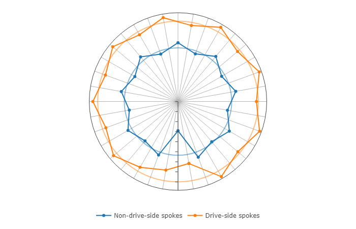
Rear wheel with radial/3-cross spoke pattern
Some wheelbuilders advocate using a different spoke pattern on the drive side and non-drive side. For example, using radial spokes on the drive-side can slightly increase the spoke angle, and therefore decrease the difference between DS and NDS tensions. This means that virtually all of the torque is transferred by the NDS spokes.
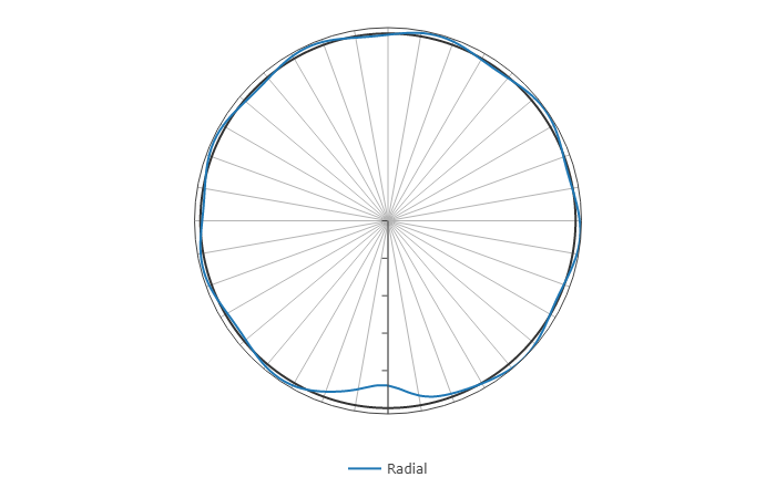
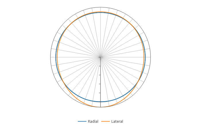
If a lateral load is added (maybe due to skidding or tipping the bike while traveling forwards), the spokes increase in tension on one side and decrease on the other side to balance the side load. The wheel is very flexible in the lateral direction and lateral loads can easily cause spokes to buckle or the rim to collapse. In this case, the lateral deformation is so large that the radial deformation cannot be seen in the plot at all.