How to use the Bicycle Wheel App
The Bicycle Wheel App is a tool for designing and simulating a virtual bicycle wheel. Calculate stiffness, mass, and rotating inertia, and see how spoke tensions change when you apply forces to the wheel or adjust spoke nipples.
Coordinate system
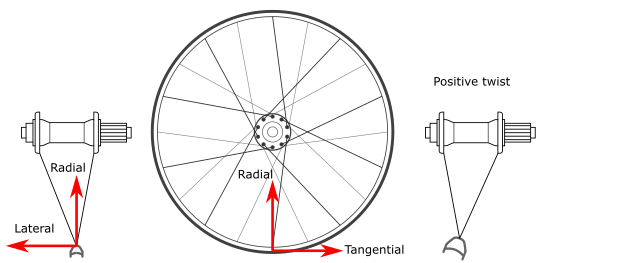
Forces and deformation are both specified in terms of three directions: radial, lateral, and tangential. The positive radial direction points inwards towards the center of the hub. The positive lateral direction points towards the non-drive side (NDS) of the bike. The positive tangential direction points along the rim in the counter-clockwise direction (forwards, at the road contact point). Positive rim twist is defined as a right-handed rotation around the tangential direction (imagine pointing your thumb along the tangential direction, and curling your fingers: that's the direction of positive rim twist).
The bottom-most spoke is a non-drive-side leading (pushing) spoke. The spokes alternate NDS, DS, NDS, ... and leading, leading, trailing, trailing...
Designing your wheel
Design your wheel by selecting options for the rim, hub, and spokes.
Rim tab
You may choose from a short list of rims which have already been characterized, or design your own from scratch. The app does not perform any checks to ensure that your rim is feasible. For guidance on the values below, try choosing some presets to see what values they have.
Material: The material sets the density, the Young's modulus, and shear modulus. The density, together with the wheel size and mass, determines the cross-sectional area of the rim. The cross-sectional area generally has a very small effect on the mechanical behavior. The Young's modulus and shear modulus are already incorporated into the bending stiffnesses, and therefore have no direct effect on the mechanical behavior of the wheel.
Wheel Size: Select from a list of standard wheel sizes. This determines the radius of the rim. All else held equal, small wheels are inherently stiffer and stronger than large wheels.
Mass: The mass of the rim has a negligible effect on the mechanical properties (unless it is very small), but has a large effect on the inertial properties of the wheel.
Radial stiffness: The radial bending stiffness is the resistance of the rim cross-section to bending within its initial plane (think of a rim being squashed top-to-bottom). It is the product of the Young's modulus and the second moment of area of the rim cross-section in the radial direction. Deep rim sections have a higher radial stiffness than shallow rim sections.
Lateral stiffness: The lateral bending stiffness is the resistance of the rim cross-section to bending out of its initial plane (think of a rim being bent sideways). The lateral stiffness and torsional stiffness are coupled and both contribute to out-of-plane deformation. The overall lateral stiffness will be dominated by the lower of the two. The lateral stiffness is the product of the Young's modulus and the second moment of area of the rim cross-section in the lateral direction. Wide rim sections have a higher lateral stiffness than narrow rim sections.
Torsional stiffness: The torsional stiffness is the resistance of the rim cross-section to twisting about its own centerline. As noted above, lateral deformations generally involve both lateral bending and twisting of the rim. The torsional stiffness is the product of the shear modulus and the torsion constant of the rim cross-section. The torsional stiffness is almost always smaller than the lateral bending stiffness, so it generally dominates the lateral stiffness of the wheel. Double-wall rims generally have much higher torsional stiffness than single-wall rims.
The rims included in the app were measured using the acoustic measurement technique developed by Ford, et. al.. The measured stiffnesses were rounded to convenient values.
Hub tab
Rim-to-flange distance: Specify the hub flange positions (lateral distance from the rim center-plane to each hub flange) for the drive side and non-drive side. If the Symmetric option is selected, drag either slider and the other will automatically mirror it. If the Symmetric option is not selected, you may independently set each flange position. Rear wheels and disc-brake wheels are commonly asymmetric due to the extra width needed for the sprocket or disc on one side of the hub. The flange position should be smaller on the side with the sprockets or disc.
Note: The app assumes that all the spoke heads on a given flange have the same lateral position. This is not strictly true since inbound and outbound spokes will have slightly different lateral angles.
Flange diameter: Specify the hub flange diameter (the diameter of the circle of spoke holes). Increasing the flange diameter increases the wind-up stiffness of the wheel, but otherwise has little effect.
Note: The hub is assumed to be rigid. For radial and lateral forces, this is a reasonable approximation as long as the flange diameter is small compared to the diameter of the wheel. However, a real hub has some torsional flexibility which can result in more torque being transmitted through the drive-side spokes than the non-drive-side spokes.
Spokes tab
Number of spokes: The total number of spokes in the wheel. This number must be even since there must be an equal number of spokes on the drive side and non-drive side.
Spoke pattern: Choose the spoke arrangement for the wheel. Increasing the number of crossings increases the torsional stiffness of the wheel dramatically, but slightly decreases the lateral and radial stiffness.
Note: A radial-spoked wheel with no spoke tension has theoretically zero torsional stiffness, which leads to a "Linear algebra error." Add at least 1 kgf of tension in order to correct the error.
Material: The material sets the density and Young's modulus of the spoke material. Stainless steel (very common) has a Young's modulus of approximately 210 GPa. Aluminum and titanium are significantly less stiff (69 GPa and 105 GPa, respectively), but are also less dense.
Diameter: The effective average diameter of the spoke. For a straight-gauge spoke, this is simply the diameter. For a bladed spoke, the effective diameter is d_eff = sqrt(1.273 * area), where area is the cross-sectional area. One could estimate the cross-sectional area by weighing a single spoke, knowing the density and length, or by measuring the short and long widths and approximating the cross-section as an ellipse. The effective diameter for butted spokes is more complicated, but is generally close to, but larger than the diameter of the thin section.
Spoke tension: Set the average tension in each spoke, in kgf. On a symmetric wheel, the drive-side and non-drive-side tension will be equal. On an asymmetric wheel, the tension will be higher on the side with the smaller rim-to-flange distance (i.e. the drive-side on a typical rear wheel). The app will automatically calculate the correct tension for the opposite side, regardless of which slider you control.
Applying forces
Apply external forces to the rim either by choosing from preset force scenarios (e.g. "Weight," "Pedaling torque," etc), or by adding your own force using the table. To add a preset force scenario, select a scenario from the dropdown list and it will be automatically added to the table. Note that adding a scenario does not remove previously added scenarios. The "Weight" scenario is already added by default. If you add it again, the total weight applied will be doubled.
Add your on forces manually by clicking on the plus sign at the bottom of the forces table. To edit an existing force, click on any cell in the forces table. Clicking on the force type (Radial, Lateral, or Tangential) will cycle through the available types. Clicking on the Loc. or Mag. values will allow you to enter custom values. The location is specified in degrees counter-clockwise from the bottom of the wheel. The magnitude is specified in units of kgf. To remove a force, click on the trash icon to the right.
For the purposes of adding forces and calculating deformation, the hub acts as a rigid reference point. Whatever forces are applied to the rim, the solver will automatically constrain the hub using whatever combination of forces and torques are necessary to keep the wheel in mechanical equilibrium. You cannot directly apply forces to the hub. This means, for example, that to simulate a drive torque, you must apply a positive tangential force at 0 degrees equal to the torque divided by the rim radius.
Note: To apply a braking force with a disc brake, apply a single, negative tangential force at 0 degrees (the ground). The torque from the disc will automatically be applied to the hub. To apply a braking force with a rim brake, apply a negative tangential force at 0 degrees, and an equal but positive tangential force at 180 degrees (the brake pads). Both of these scenarios are included as force presets
Adjusting spokes
You can also use the app to see what happens when you tighten or loosen spokes. Specify spoke adjustments in the bottom table on the Forces tab. To add an adjustment, click or tap the plus sign and then tap the "Spoke Number" and "Number of turns" fields to edit. Spoke numbers run from 1 (bottom-most spoke) up to the specified number of spokes, increasing counter-clockwise. The "Number of turns" is converted to a change in unstressed spoke length using a thread pitch of 56 TPI (thread-per-inch). A positive number indicates an adjustment that tightens the spoke.
Interpreting results
Tensions plot
The spoke tensions can be viewed as a Polar plot or a Column plot. Spoke tensions are given in kgf (kilogram-force) units. Tensions less than zero cannot be shown on the polar plot. The initial tensions in the undeformed wheel are shown as blue and orange circles. In the column plot, you can view either the Absolute tension, or the Difference in tension between the stressed and unstressed wheel. Negative values in the Difference plot indicate a loss of tension. The bottom-most spoke is plotted in the middle of the column plot.
The solver does not properly account for the loss of stiffness that occurs when a spoke completely loses tension. If the solution contains any negative tensions, the app will raise a warning.
Hover your mouse over (or tap) any datapoint to see its value
Deformation plot
The deformation plot shows the distortion of the rim in each direction. Click or tap the Radial, Lateral and Twist toggle buttons to add or remove traces from the plot. Radial deformation refers to distortion of the rim in its own plane. Lateral deformation refers to movement of the rim out of its plane. Twist refers to rotation of the rim cross-section, relative to its initial position. Since twist has units of angle (radians), twist is plotted as radius*twist so that it has the same units as radial and lateral deformation.
In the Polar plot, the deformation is plotted as deviations from a unit circle. The deformations are scaled so that the largest displacement is equal to the scale factor. For lateral deformation, positive deviation means movement towards the non-drive side of the wheel. For twist deformation, positive deviation means rotation of the cross-section in the same sense as a positive lateral deviation (think of the rim cross-section as a pendulum rotating about the hub: as the pendulum swings to the one side, the bob also rotates in the same direction).
In the Line plot, the deformation is plotted in units of millimeters. The x-axis corresponds to length along the rim, as if the rim had been cut at the top and unrolled into a straight line. Use the line plot if you need to read quantitative results.
If you accidentally rotate or zoom any plot by clicking on or touching it, double-tap on the plot to return to the default view.
Summary results
The app calculates the inertial properties and stiffness of the wheel.
Mass: Mass of the rim and spokes ONLY (the hub, spoke nipples, tire, tube, etc are excluded). This is the mass that you "feel" when climbing a hill at a constant velocity.
Eff. rotating mass: Since the wheel rotates as well as translates, it requires more energy to accelerate, per gram, than the frame or rider. The effective rotating mass is the equivalent mass which would require the same amount of energy to bring to the same velocity as the rotating wheel. This is the mass that you "feel" when accelerating the bike.
The effective rotating mass cannot theoretically exceed 2x the mass of the wheel, and cannot be less than 1.333x the mass of the wheel.
Radial stiffness: The radial force, applied at 0 degrees, which would produce a unit displacement in the radial direction.
Lateral stiffness: The lateral force, applied at 0 degrees, which would produce a unit displacement in the lateral direction. This is the stiffness famously measured by Damon Rinard.
Torsional stiffness: The force, applied at 0 degrees, which would cause the hub to rotate by 1 degree relative to the rim. This is not related to the torsional stiffness of the rim. The torsional stiffness of the wheel is almost entirely determined by the spoke pattern and properties.
Drive-side/Non-drive-side tension: Spoke tensions on each side of the wheel, in kgf.
Average tension: The average radial tension acting on the rim. This is the average tension supported by the rim. The average tension is slightly less than then the tension on either side (in a symmetric wheel) because the spokes are not perfectly radial.
Maximum average tension: The rim can only withstand a certain amount of tension without buckling. The maximum average tension is the theoretical average radial tension which would cause the rim to taco during building. In practice, you can generally get to about half of the theoretical tension before the rim becomes too distorted. Jobst Brandt [2] advocated using this method to determine the proper tension for a wheel. The maximum tension is calculated from Equation 4.4 in reference [1].
Lateral/Radial force to buckle spokes: The maximum force that can be applied before the first spoke buckles. Beyond this point the wheel will lose stiffness and strength.
Lateral forces are usually also accompanied by a radial force (due to the weight of the bike and rider). Therefore the actual lateral force to buckle spokes would be reduced if a radial load is present.
Notes regarding the solver
The full modeling assumptions and derivations underlying the app are described in detail in my Ph.D. thesis: Reinventing the Wheel: Stress Analysis, Stability, and Optimization of the Bicycle Wheel. The app uses the Mode Matrix Model described in Section 2.4.1 of the thesis.
The mechanical properties and deformations are calculated using my Bike Wheel API. The API accepts options in JSON format and returns a JSON object with the results. The API is built in Python and runs on Amazon AWS Lambda. The Bike Wheel API is just a wrapper for my Python library, bike-wheel-calc.
Got feedback? Found a bug?
This app is VERY much a work in progress. The code for the app and website is available on GitHub. If you find bugs or want to suggest features, log an issue or contact me at mford <at> u.northwestern.edu.
References
[1] Matthew Ford, Reinventing the Wheel: Stress Analysis, Stability, and Optimization of the Bicycle Wheel, Ph.D. Thesis, Northwestern University (2018)
[2] Jobst Brandt, The Bicycle Wheel, Avocet (1993).